Cartridge kit#
Introduction#
This project is a cost-reduced version of the Multicartridge, meant for hobbyist who would like to build their own cartridge and are comfortable using a soldering iron. The cartridge is designed such that the majority of the components can already be assembled by the PCB manufacturer (e.g. using a so-called assembly service). The user only needs to solder in three more through-hole components and the cartridge is ready to use.
Note
To understand how the cartridge works, see the explanation as found in the Multicartridge article. Here, we will only explain how the kit is assembled.
Caution
Give this page a thorough read before you start soldering.
Ensure you are mounting the components on the right side of the PCB. Have a careful look at the pictures. Removing a component once soldered is relatively difficult.
All fingers of the edge connectors are numbers. If the numbers end in “a”, you are looking at the A-side of the board. IF the numbers end in a “b”, you are looking at the B-side.
Components#
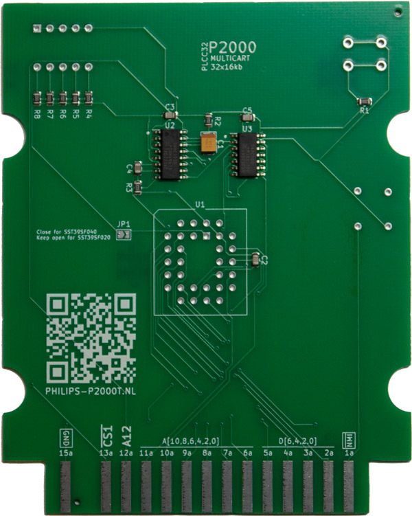
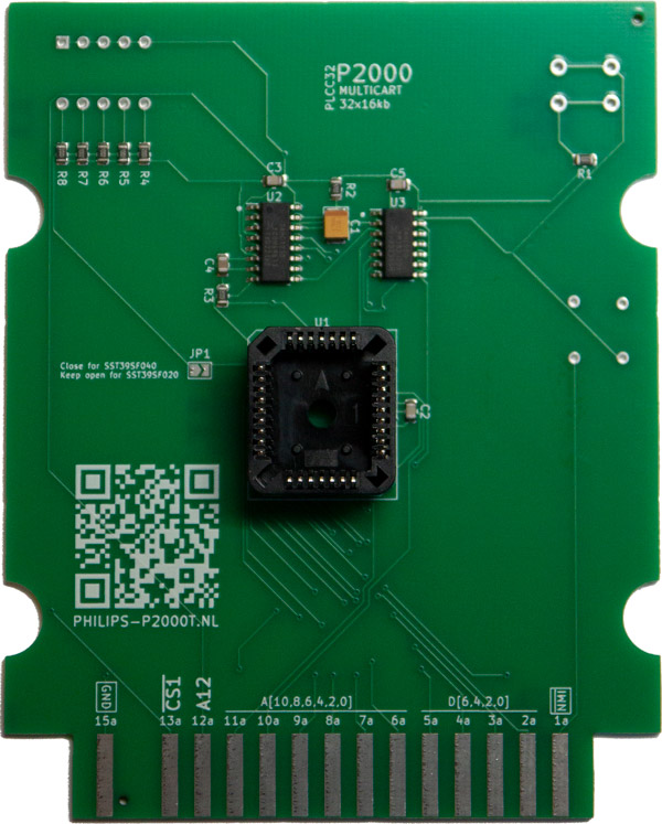
Before starting building your cartridge, check that all components are present. You need one PCB with the majority of the SMD components already soldered as shown in Figure 18a.
Furthermore, you need the following three through-hole components (see Figure 18b):
PLCC32 socket
DIP switch
Push button
 a
a
 b
b
Fig. 18 (a) P2000T kit PCB; (b) THT components#
Soldering guide#
Note
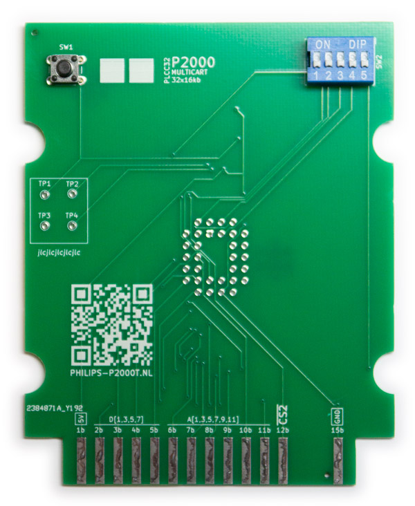
The PCB has two sides: side A and side B. These sides correspond to sites A and B of the P2000T cartridge. Side A contains all the SMD components and will be facing away from the user when inserted into the P2000T. Side B has two white squares on the soldermask and will be facing towards the user when inserted in the P2000.
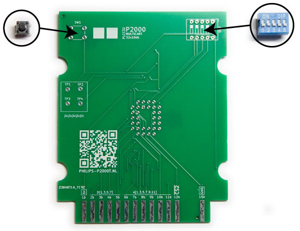
Insert the tactile push button and the DIP switch on side B of the PCB in SW1 and SW2, respectively, and solder the pins (see Figures Figure 19a and Figure 19b).
 a
a
 b
b
Fig. 19 (a) Position of the tactile push button (SW1) and the DIP switch (SW2); (b) Tacile push button (SW1) and DIP switch (SW2) mounted on the PCB#
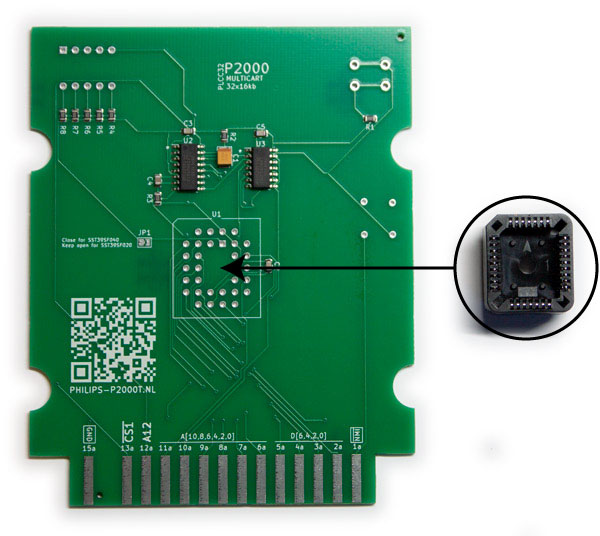
Insert the PLCC32 socket on side A of the PCB in U1 and solder the pins.
 a
a
 b
b
Fig. 20 (a) Position of the PLCC32 socket (U1); (b) PLCC32 socket (U1) mounted on the PCB#
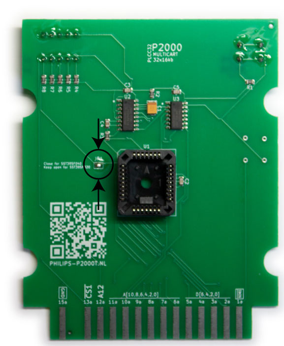
If you intend to use the 512kb SST39SF040 chip, place a solder blob on JP1 such that both ends are shorted.
 a
a
 b
b
Fig. 21 (a) Position of the jumper pad (JP1); (b) Solder blob placed on the jumper pad (JP1)#
Carefully inspect your solder points to see if they look properly and you are all done.
Casing (optional)#
The PCB can be nicely embedded in a 3d-printable case, as found here. The recommended settings for the prints are:
0.4mm nozzle
0.15mm layer height
20% infill
For the casing, you need:
4 M3 threaded inserts
4 M3x8mm screws
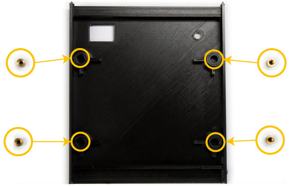
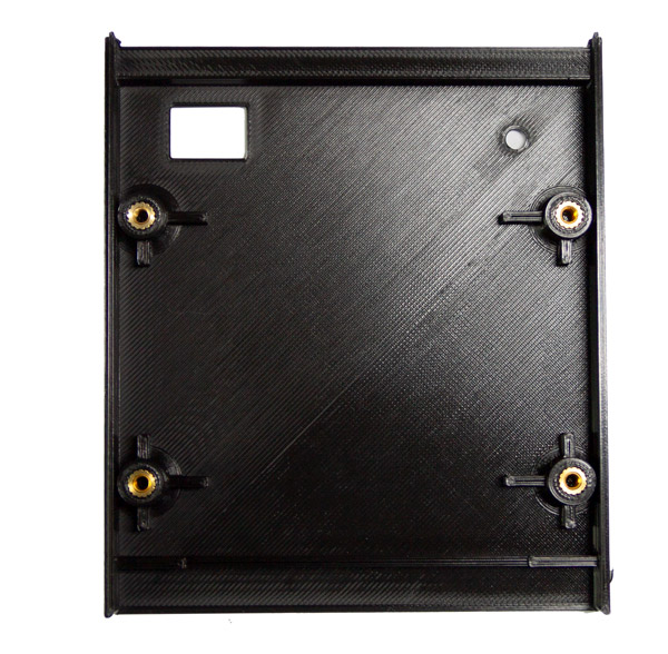
Heat up your soldering iron to and gently push the threaded inserts into the plastic holes of the top side of the case as shown in Figure 22a and Figure 22b.
 a
a
 b
b
Fig. 22 (a) Position of the holes for the threaded inserts; (b) The threaded inserts fixed in the case#
Place the PCB inside the top case and gently push it until it snaps into place. Ensure that the A side, i.e. the side containing the chips, is facing towards you and that the push button and the dip switch are on the opposite side, as shown in Figure 23.
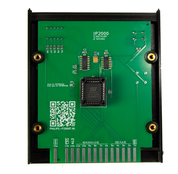
Fig. 23 PCB inserted into the top part of the case.#
Tip
Do not forget to insert the PLCC32 chip before closing the cartridge.
Check once more whether you closed the jumper pad JP1 if you are using the SST39SF040 chip or leave it open when you are using a SST39SF020 chip.
Align the bottom half of the cartridge enclosure with the top and gently apply pressure until they both half snap together. Insert the four M3x8mm screws (see Figure 24a and Figure 24b) and fasten them.
 a
a
 b
b
Fig. 24 (a) Positions of the M3x8mm screws; (b) The M3x8mm screws inserted into the cartridge#
That is it. You are done. Turn over the cartridge and admire your work.
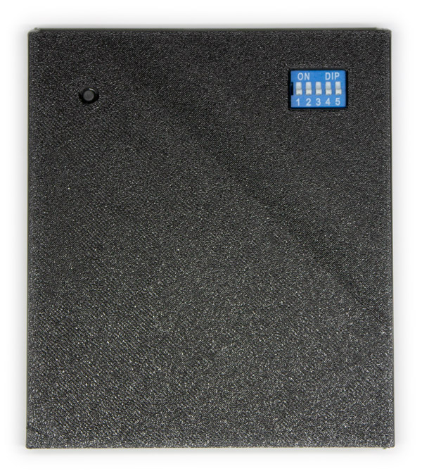
Fig. 25 The complete cartridge.#